
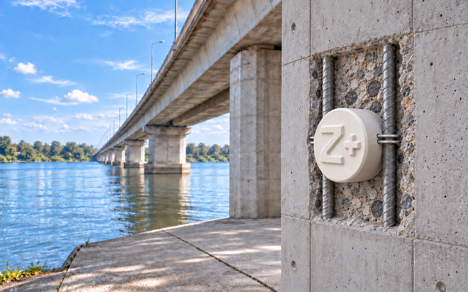
 Embedded Galvanic Zinc Anode
Corrosion Protection for Reinforced Concrete Structures
A corrosion protection system for reinforcing steel in concrete, engineered by corrosion engineers, with full service from design through hand-over.
- ✓Protects reinforcing steel inside concrete
- ✓Designed by corrosion engineers
- ✓Certified to TIS 3029-2563 · ASTM B418 Type II · ISO 12696
- ✓One-stop engineering solution from a single manufacturer
Patching the surface alone
doesn't control corrosion at the root cause
Removing and re-patching only the damaged area turns the perimeter of the repair into a new anode (the Ring Anode Effect / Incipient Anode). The reinforcing steel around the repair edge then corrodes faster and cracks again within a few years. Installing SmartZinc Z+ alongside the repair addresses the electrochemical root cause, not just the surface.
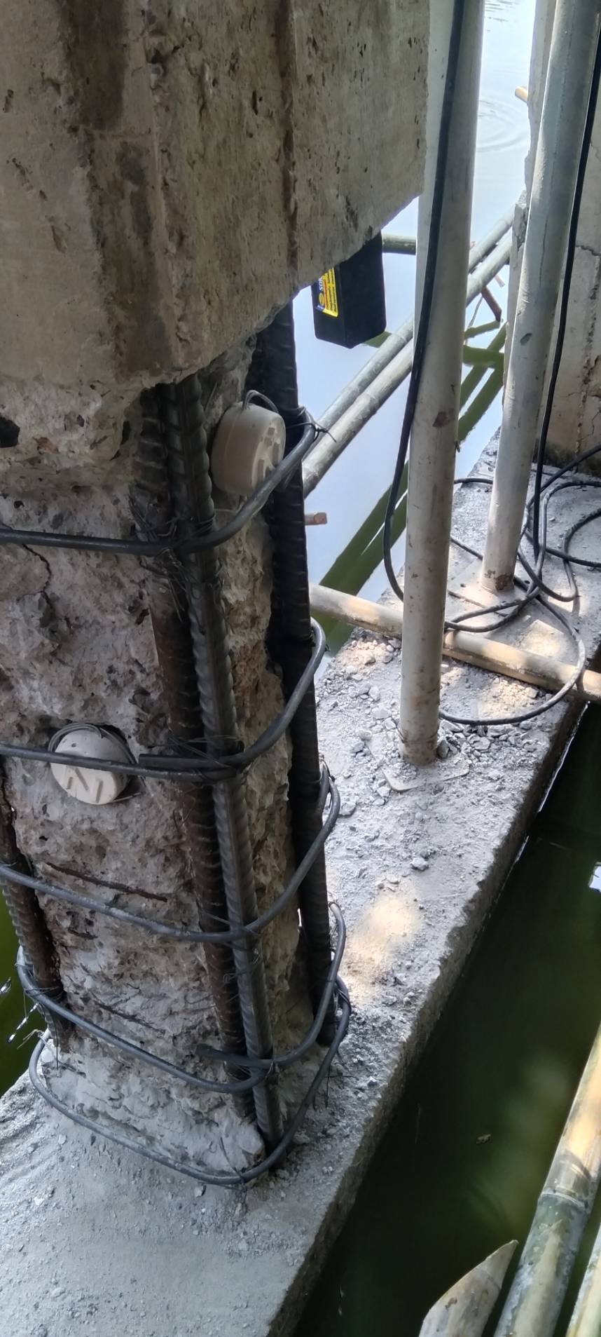
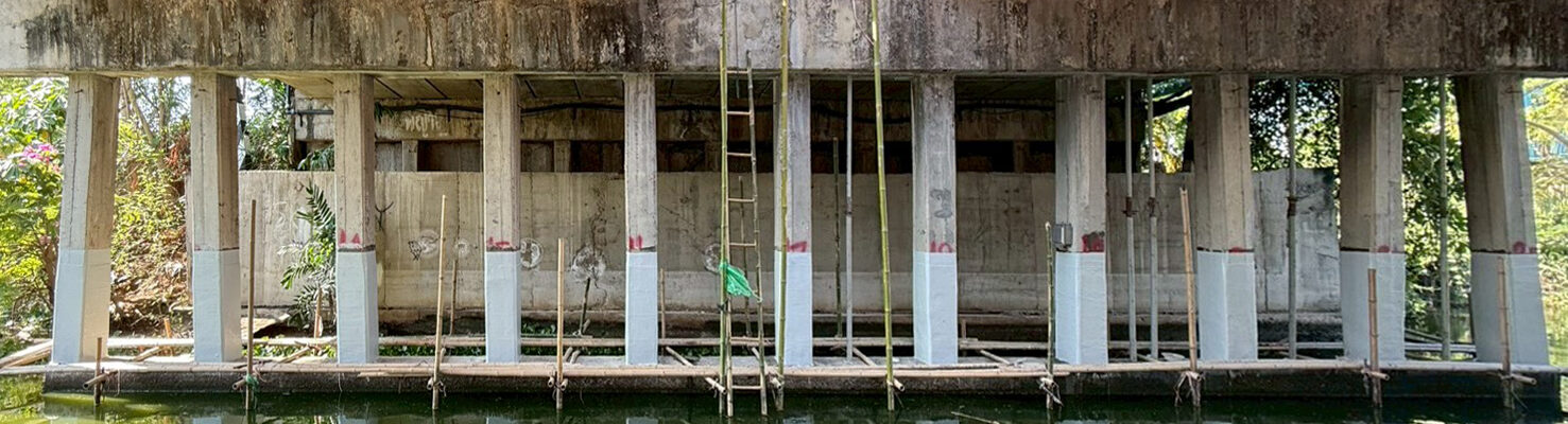
DRAG TO COMPARE
Phim Thong Village project, the same column, before removal & repair / after installing SmartZinc Z+ and patching
* Service life is a design value, depending on model, quantity, spacing, environment, rebar density and the engineer's design calculations
Concrete structures don't fail because of concrete
They fail because the reinforcing steel inside is rusting
Corrosion of reinforcing steel is the leading cause of damage in reinforced concrete structures, and it's invisible damage, undetectable until the concrete starts to crack, which is exactly when repair costs are highest.
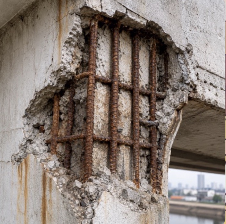 P01
P01
Concrete Spalling
When concrete spalls, the problem isn't just the surface
Rust forming inside the reinforcing steel expands, pushing the concrete apart until it cracks and spalls, affecting strength, safety, and the structure's service life.
SmartZinc Z+ protects against corrosion from within, before the damage can spread.
 P02
P02
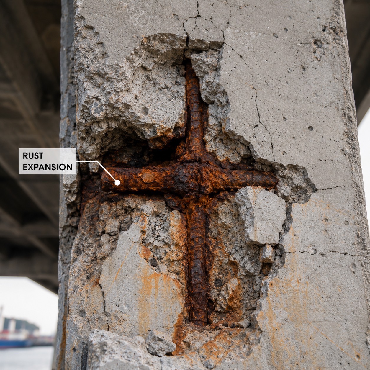
Rust Expansion
The Hidden Cause of Concrete Spalling
The expansion of rust in reinforcing steel is a major cause of cracking and concrete spalling, which accelerates corrosion, shortens service life, and increases maintenance costs.
 P03
P03
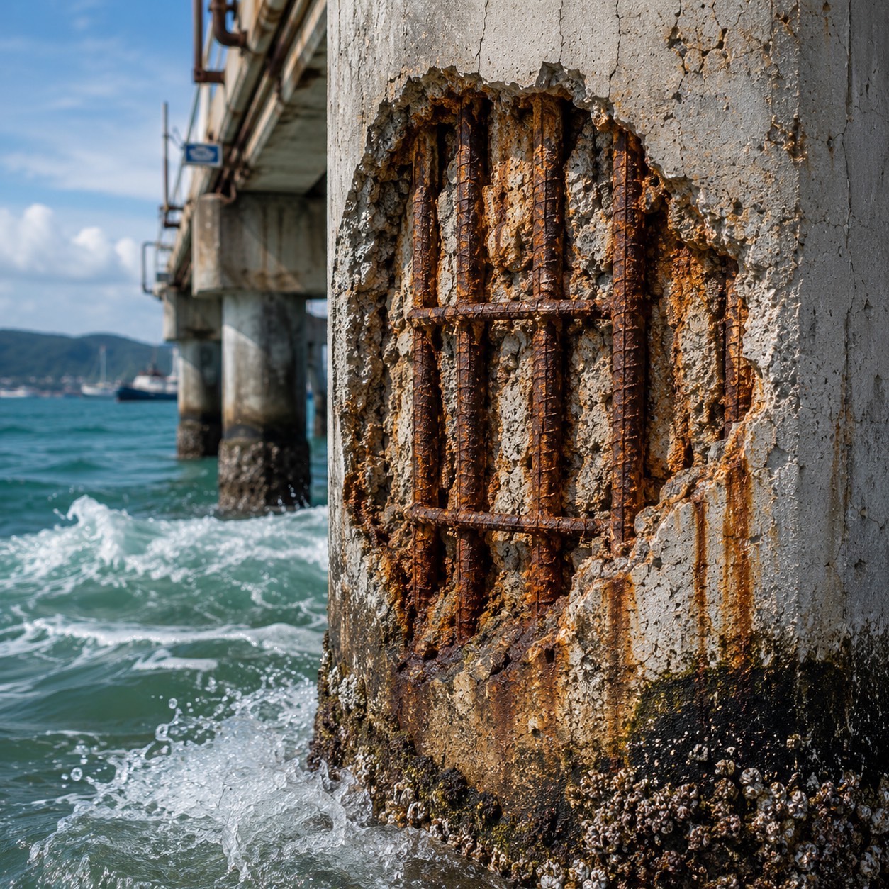
Chloride Attack
The Silent Threat That Accelerates Rebar Corrosion
Chloride from the sea, saltwater, and salt-laden environments can penetrate concrete, destroy the reinforcing steel's protective layer, and accelerate rust formation from within the structure.
 P04
P04
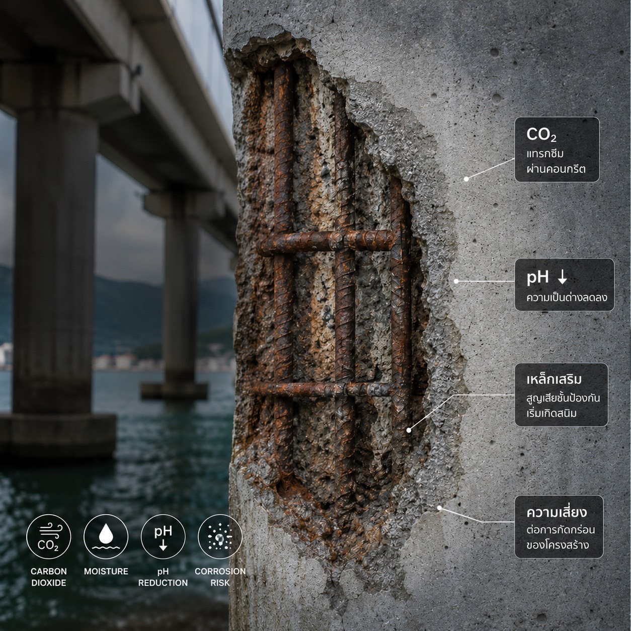
Carbonation
The Silent Threat That Reduces Rebar Protection
Carbon dioxide (CO2) gradually penetrates concrete, lowering its alkalinity, causing the reinforcing steel to lose its protective layer and begin corroding from within.
 P05
P05
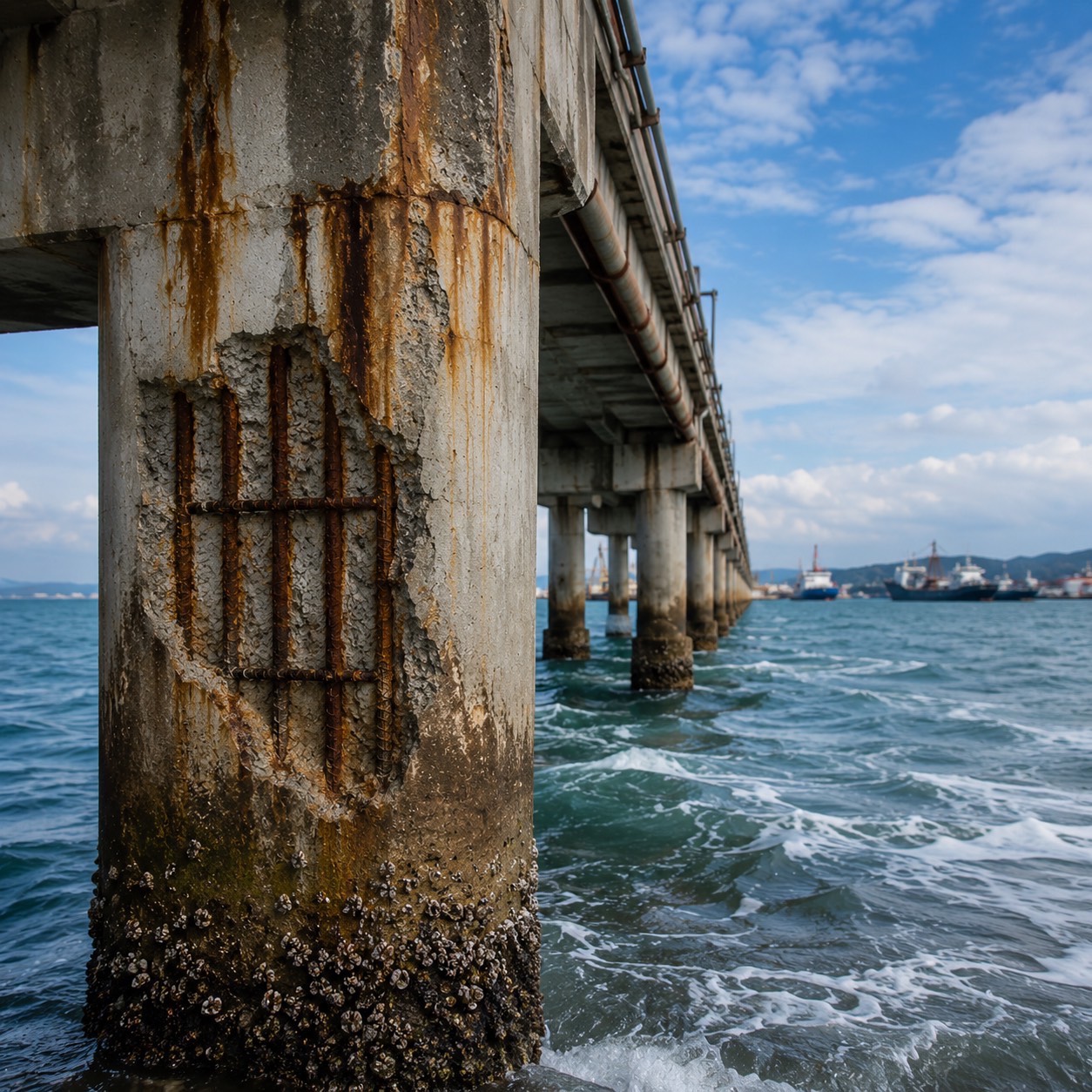
Marine Environment
Protecting Structures Before Corrosion Begins
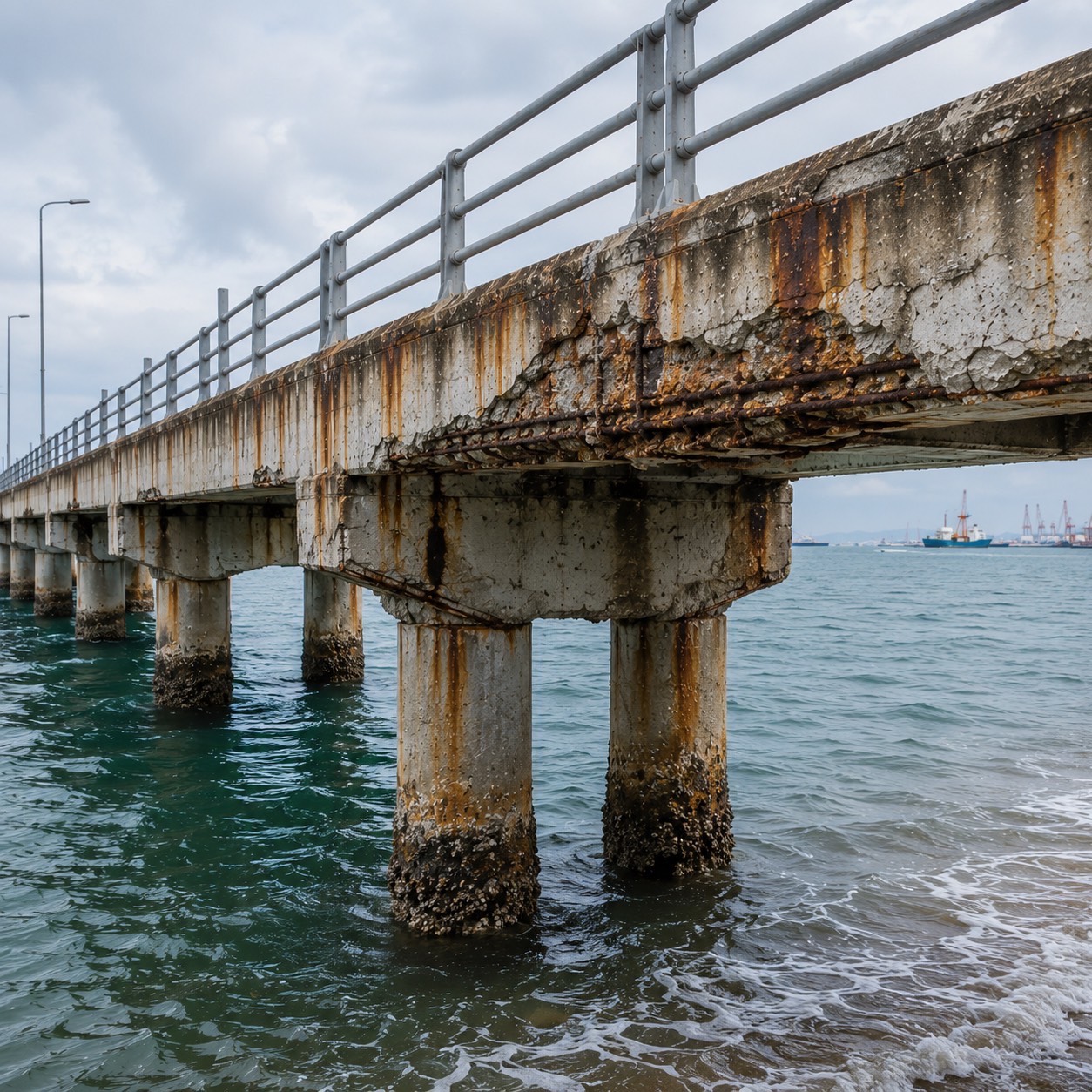
Structures along coastlines, ports, and the sea face constant chloride, moisture, and sea spray, key factors that accelerate corrosion of reinforcing steel and shorten a structure's service life.
 P06
P06
Parking Structure
Protecting Parking Structures Before Corrosion Begins
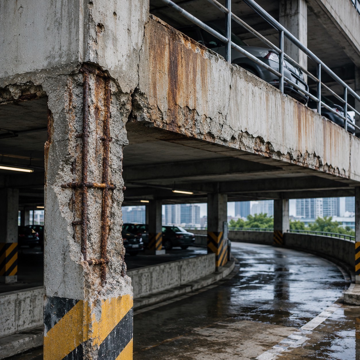
Parking structures face constant moisture, chloride, and cracking from daily use, accelerating rebar corrosion and concrete spalling, and shortening the structure's service life if not protected from the start.
 P07
P07
Water Treatment
Protecting Structures in Highly Corrosive Environments
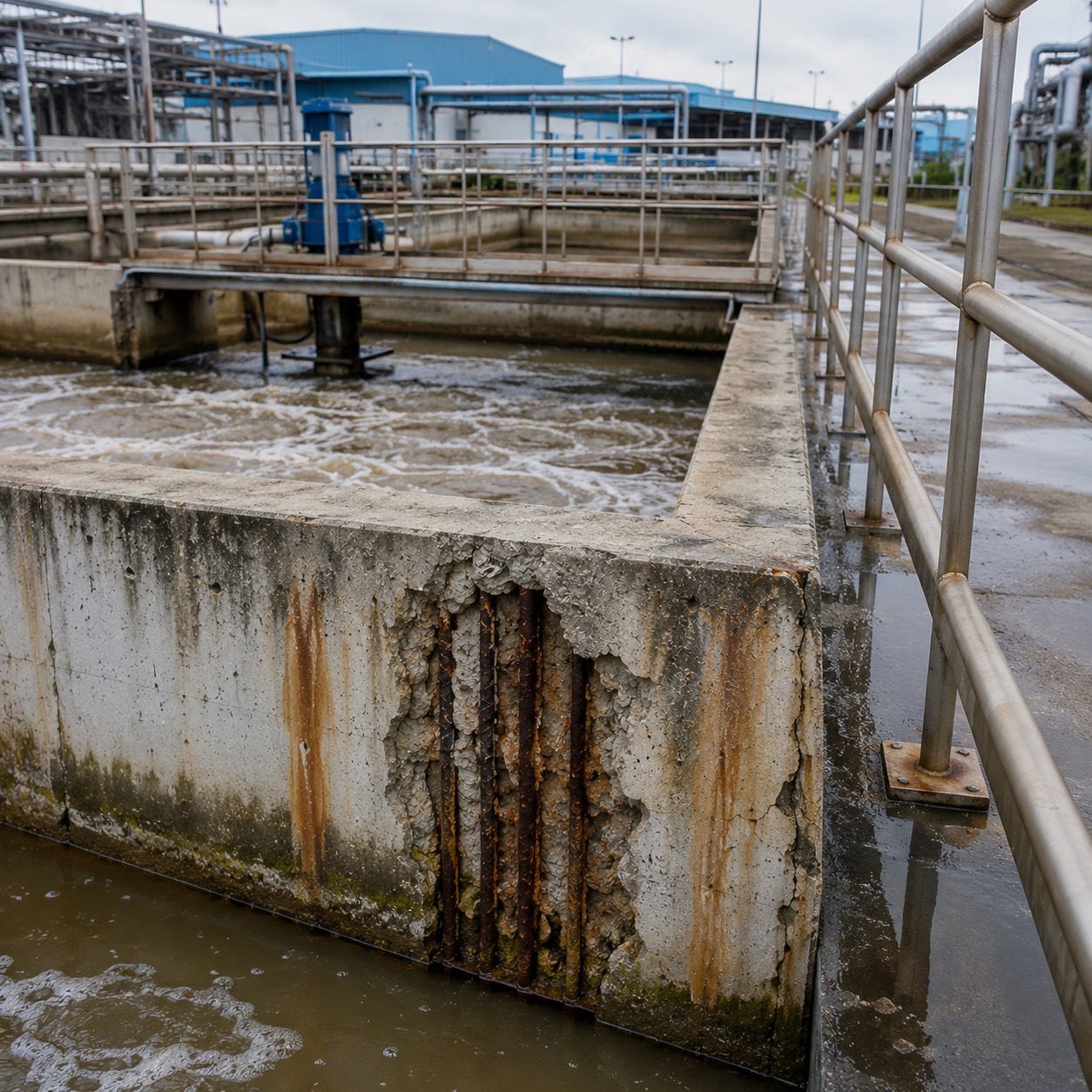
Concrete structures in wastewater treatment plants face constant moisture, chemicals, and corrosion, accelerating rebar corrosion and concrete deterioration, and shortening the structure's service life if not protected from the start.
 P08
P08
Bridge Deck
Protecting Bridges Before Corrosion Shortens Their Service Life
Bridge decks face constant moisture, chloride, and weather exposure, accelerating rebar corrosion and concrete spalling, and reducing the structure's durability if not protected from the start.
How Reinforcing Steel in Concrete Rusts
Under normal conditions, concrete is highly alkaline (pH around 12–13), which forms a thin passive film coating the reinforcing steel's surface, so the steel does not rust even in moist conditions. This film is the natural protective armor of a reinforced concrete structure.
This armor is destroyed in two main ways: chloride attack from seawater, salt spray, or chemicals reaching a critical concentration at the steel's surface, and carbonation, where CO2 reacts with the alkalinity in concrete until pH drops below 9. Once the passive film is gone, spots on the steel surface become an anode that releases electrons, while neighboring areas become a cathode: forming a corrosion cell inside the concrete.
Why Rust Causes Concrete to Crack and Spall
Corrosion products (iron oxide/hydroxide) occupy roughly 2 to 6 times more volume than the original steel, depending on the type of rust formed. This expansion happens inside a fixed volume of concrete, generating very high internal pressure.
Since concrete can only withstand about 10% of its compressive strength in tension, the pressure from rust causes, in sequence: cracking along the rebar → delamination → concrete spalling. At the same time, the reinforcing steel's cross-sectional area shrinks, reducing the structure's load-bearing capacity and safety.
What Is Cathodic Protection?
Cathodic Protection (CP) is the principle of controlling corrosion by making the metal to be protected entirely a cathode. When reinforcing steel is the cathode, the dissolution reaction of the steel (Fe → Fe²⁺) is suppressed, so corrosion is controlled even while chloride remains in the concrete. This is why CP is internationally recognized as able to control corrosion that has already begun, without needing to remove all chloride-contaminated concrete.
The international standard for designing CP systems for steel in concrete is ISO 12696:2012 (Cathodic Protection of Steel in Concrete), which sets performance verification criteria such as Polarization Decay ≥ 100 mV within a specified time.
- Galvanic / Sacrificial Anode CP: uses the natural potential difference between metals, requires no external power, is easy to install, and needs little maintenance, suited to spot repairs and general structures.
- Impressed Current CP (ICCP): uses an external DC power supply with a permanent anode, delivering high, adjustable current, but requires a control cabinet, monitoring system, and ongoing maintenance for the system's life.
This is a performance verification criterion under ISO 12696: the protection circuit is interrupted and the reinforcing steel's potential recovery is measured. If the potential changes (decays) by 100 mV or more within the specified time, the steel has been sufficiently polarized to genuinely control corrosion. SmartZinc Z+ delivers a Polarization Decay greater than 100 mV within 24 hours per test results.
How Galvanic Protection Works
Every metal has a different natural electrical potential, ranked in the Galvanic Series. When two metals with different potentials are connected in an electrolyte (here, the pore solution inside concrete), the metal with the more negative potential becomes the anode and corrodes in place of the other, which is protected.
Zinc has a distinctly more negative potential than steel. When SmartZinc Z+ is tied and electrically connected to the reinforcing steel, the zinc sacrifices itself to corrosion first, continuously supplying protective current to the steel, with no external power source required.
Why Engineers Prefer Zinc Anodes
Zinc provides a potential difference well matched to steel in concrete, strong enough for genuine protection, but not so strong as to risk hydrogen embrittlement in high-strength steel. This is unlike externally powered systems, which require constant, careful current control.
SmartZinc Z+ encases its zinc core in high-alkalinity cement mortar (pH ≥ 14), which keeps the zinc consistently active throughout its service life, delivering continuous, predictable current without passivating and shutting down.
- No wiring, no control cabinets, and no electricity cost over the system's service life.
- Can be installed alongside concrete repair work immediately, without long area shutdowns.
- Directly controls the Ring Anode Effect at the boundary between existing concrete and repair material.
- Needs almost no maintenance, suited to owners without a dedicated electrical maintenance team.
- Service life can be designed via zinc weight and spacing, calculable and verifiable to ISO 12696.
Ordinary repair mortar only restores shape and seals the concrete surface. It does not change the electrochemical state of the reinforcing steel, so steel around the repair keeps corroding. SmartZinc Z+, by contrast, is a Galvanic Cathodic Protection system that continuously supplies protective current to the reinforcing steel long after the repair is closed up.
Zinc Sacrifices Itself First
So the Reinforcing Steel Survives
Scroll to see the actual electrochemical process happening inside the concrete, from the moment steel begins to corrode, through to verification with standard measuring instruments.
Steel begins to corrode
When chloride or carbonation destroys the passive film, spots on the steel surface become an anode and begin releasing charge. Rust forms and expands, pushing the concrete until it cracks, while the outer concrete surface may still look normal.
⚠ CORROSION INITIATED · No visible external warningSmartZinc corrodes first
SmartZinc Z+ is tied to the reinforcing steel with 2 lead wires at 4 points. Once the circuit is complete, the zinc, with its more negative potential, becomes the anode instead, and begins corroding itself to supply current to the reinforcing steel.
⚡ Zn → Zn²⁺ + 2e⁻ · No external power requiredSteel remains protected
Current flowing into the reinforcing steel turns the entire bar into a cathode. The steel's dissolution reaction is suppressed and corrosion stops spreading, while the Ring Anode Effect around the repair area is controlled within the designed radius.
🛡 PROTECTION RADIUS ≥ 500 mm per TIS test resultsVerified & documented
The engineer measures electrical continuity (< 0.1 Ω) and Polarization Decay to confirm the system genuinely performs to the ISO 12696:2012 criteria, recording results in QC documentation and As-Built records handed over to the project owner.
✓ POLARIZATION DECAY ≥ 100 mV / 24HChoose the Right System
from Day One
Four main approaches to controlling corrosion of reinforcing steel, mapped on the two factors project owners actually decide on: protection effectiveness and life-cycle value.
Paid once alongside repair work, no electricity cost, no system upkeep cost. It helps reduce how often repeat repairs are needed compared with patching alone.
No wiring needed, no control cabinet, no team required to watch the system. It keeps working on its own.
Delivers continuous galvanic current within the designed radius, controls the Ring Anode Effect, and can be measured and verified to ISO 12696.
SmartZinc Z+
- ✓ No electricity needed, no system upkeep cost
- ✓ Can be installed alongside repair work immediately
- ✓ Certified to TIS 3029-2563 · ASTM B418
ICCP
- ✓ Finest current control of any system
- ✕ Very high installation cost
- ✕ Requires a maintenance team and electricity for its whole life
Sacrificial Steel
- ✓ Low starting cost
- ✕ Risk of losing current output ahead of schedule
- ✕ Hard to predict the protection radius
Patch Repair Only
- ✓ Fast to start, low cost per job
- ✕ Doesn't control corrosion at the root cause
- ✕ Ring Anode Effect occurs around the repair
* Service life is a design value, depending on model, quantity, spacing, environment, rebar density and the engineer's design calculations
Why Leading Infrastructure Projects
Choose SmartZinc Z+
Embedded Galvanic Zinc Anode for Reinforced Concrete Corrosion Protection
Long Service Life
Design service life up to 30 years, depending on model, quantity, spacing, environment, rebar density and the designing engineer's calculations, with no wiring needed, no control cabinet, and almost no maintenance for the system's whole life.
Proven Protection
Polarization Decay greater than 100 mV within 24 hours, per ISO 12696 criteria
Protection Radius
Minimum protection radius per TIS test results, up to 1,000 mm in the Z+160G model
Years of Experience
Over 27 years of experience in reinforced concrete repair and strengthening
Engineer's checklistWhy Engineers Choose SmartZinc Z+
Talk to an Engineer →- ✓Certified to TIS standards
- ✓Embedded Galvanic Zinc Anode technology
- ✓Protects reinforcing steel from corrosion starting inside the concrete
- ✓Multiple models covering every project type
- ✓An engineering team ready to consult and design
- ✓Full-service, from design through installation and inspection
- ✓Helps reduce maintenance costs over the structure's service life
- ✓Suited to bridges, piers, parking structures, hospitals, wastewater treatment systems, industrial plants, and infrastructure
Choose the Right Model
for Your Structure
Every model uses a high-alkalinity mortar puck (pH ≥ 14) sized 65 × 35 mm (±5) with 2 lead wires at 4 points. Switch between models instantly with no page reload.
Typical Applications
An entry-level model for repairs where corrosion risk isn't high, mainly focused on preventing the Ring Anode Effect around the repair area.
The mortar puck is 35 mm thick, so the concrete cover after installation must be at least 40 mm for it to be fully patched over.
Typical Applications
The most cost-effective choice for large installation areas, such as parking structure slabs and beams where per-square-meter budget matters.
The mortar puck is 35 mm thick, so the concrete cover after installation must be at least 40 mm for it to be fully patched over.
Typical Applications
The most popular model, balancing protection radius, service life, and cost, suited to buildings that can't be shut down for repeat repairs.
The mortar puck is 35 mm thick, so the concrete cover after installation must be at least 40 mm for it to be fully patched over.
Typical Applications
For structures that are hard to access for maintenance, or with dense rebar, needing a wide protection radius and a long service life.
The mortar puck is 35 mm thick, so the concrete cover after installation must be at least 40 mm for it to be fully patched over.
Typical Applications
The highest zinc mass for continuous, severe corrosive conditions such as tidal zones, sea spray, and chemically exposed areas.
The mortar puck is 35 mm thick, so the concrete cover after installation must be at least 40 mm for it to be fully patched over.
Concrete Cover and coverage area per anode shown for each model are approximate figures for preliminary communication only, not values to substitute for real design. Values used for actual installation must be calculated and certified by an engineer to ISO 12696:2012, combined with site survey results.
| Technical Detail | Z+60G | Z+80G | Z+100G | Z+130G | Z+160G |
|---|---|---|---|---|---|
| Pure Zinc Weight | ≥ 60 g | ≥ 80 g | ≥ 100 g | ≥ 130 g | ≥ 160 g |
| Total Weight per Anode (approx.) | ≥ 200 g | ≥ 210 g | ≥ 220 g | ≥ 235 g | ≥ 250 g |
| Protection Radius per Product | ≥ 600 mm | ≥ 700 mm | ≥ 800 mm | ≥ 900 mm | ≥ 1000 mm |
| Polarization Decay / 24h | > 100 mV | > 100 mV | > 100 mV | > 100 mV | > 100 mV |
| Mortar Puck Size | 65 × 35 mm | 65 × 35 mm | 65 × 35 mm | 65 × 35 mm | 65 × 35 mm |
| Lead Wires | 2 wires / 4 points | 2 wires / 4 points | 2 wires / 4 points | 2 wires / 4 points | 2 wires / 4 points |
| Qty per Box | 15 units | 15 units | 15 units | 15 units | 15 units |
| Recommended Risk Level | Low | Medium | Marine / High Humidity | High | Severe |
* The minimum protection radius per TIS 3029-2563 test criteria is 500 mm. Coverage area per anode is an approximate figure calculated from each model's protection radius. The actual quantity, spacing, and service life must be designed and certified by an engineer to ISO 12696:2012, combined with site survey results.
Tell Us Your Project Type
We'll Recommend a Model Instantly
No need to compare specs model by model. Choose your structure type, and the tool recommends a suitable model with preliminary engineering reasoning, as a starting point before an engineer's real calculation.
Marine Jetty
Structures in the tidal and sea-spray zone face the highest chloride concentration combined with oxygen and wet-dry cycling, the most aggressive corrosion condition for reinforced concrete work.
This recommendation is a preliminary estimate based on structure type. The actual model and quantity must be calculated to ISO 12696:2012 from site survey results.
13 Steps
Controlled at Every Point
Corrosion protection isn't just embedding a zinc puck in concrete. It's an engineering process that must be measured, recorded, and verified at every step. Choose a phase to see its steps and inspection criteria.
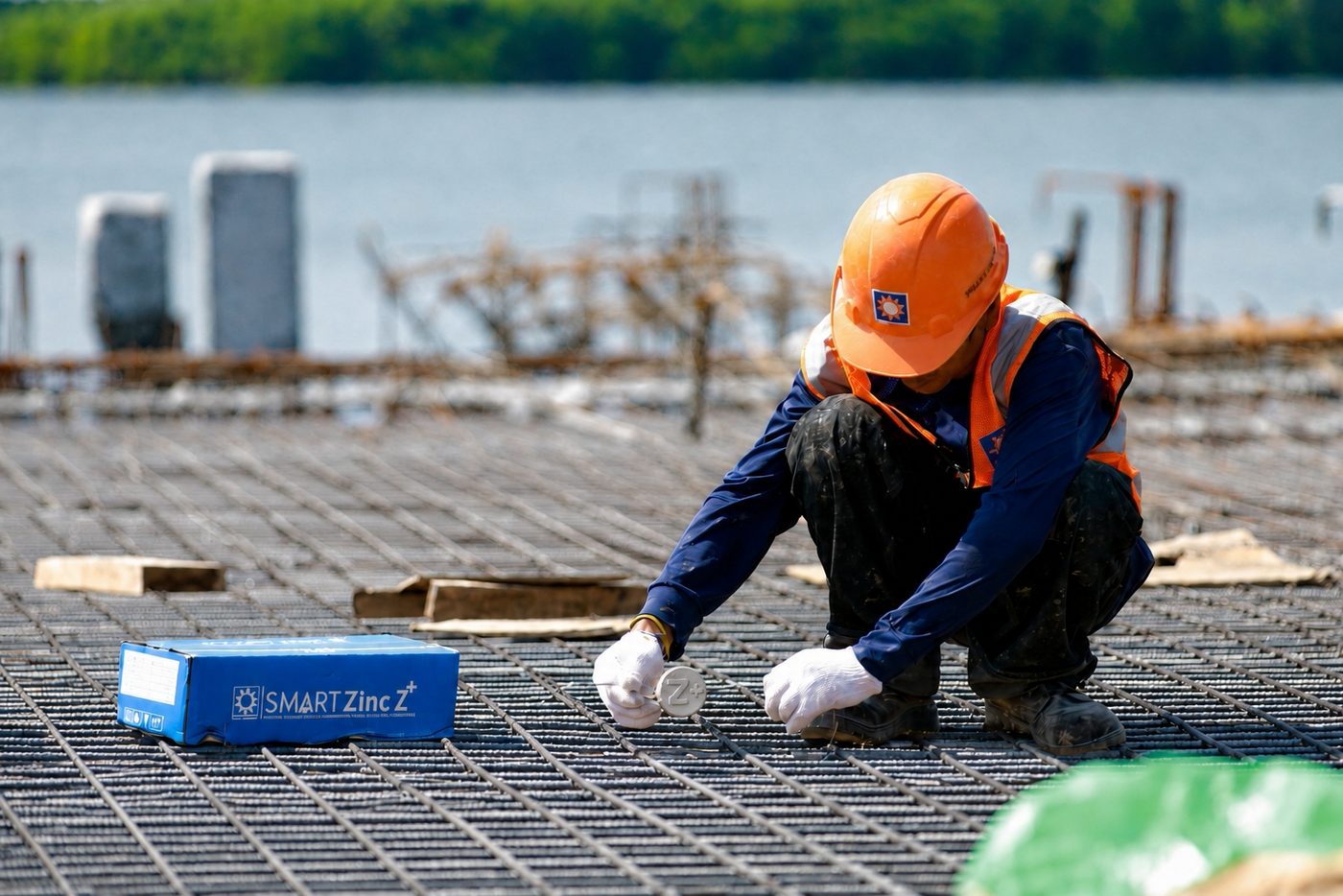
A trained field team working under an engineer's supervision, from site survey through document handover.
Site Survey & Corrosion Assessment
SITE SURVEY & CORROSION ASSESSMENTHalf-Cell Potential Survey
HALF-CELL POTENTIAL SURVEYConcrete Resistivity & Moisture Test
CONCRETE RESISTIVITY & MOISTURE TESTEngineering Design & Calculation to ISO 12696
ENGINEERING DESIGN & CALCULATIONShop Drawing & Method Statement Preparation
SHOP DRAWING & METHOD STATEMENTMarking & Removing Deteriorated Concrete
MARKING & CONCRETE REMOVALCleaning the Reinforcing Steel Surface
REBAR CLEANING & SURFACE PREPARATIONTesting Continuity of the Reinforcing Steel
CONTINUITY TESTInstalling the SmartZinc Z+ Anode
ANODE INSTALLATIONConnecting Lead Wires to the Reinforcing Steel
WIRE CONNECTION & TYINGPatching with Structural Repair Material
REPAIR MORTAR / NON-SHRINK GROUTCuring Concrete & Post-Installation Potential Measurement
CURING & POTENTIAL MEASUREMENTQC Documentation & As-Built Handover
QC DOCUMENTATION & AS-BUILT HANDOVERNeed a full Method Statement and Inspection & Test Plan for your project?
Request the Full Method Statement →A Good System
Must Prove Itself With Numbers
We don't just say the system works. We measure it for you, both before and after installation, to international standard criteria, delivering fully traceable measurement results.
Real Projects
Across Every Structure Type
From seaside piers and structures over canals, to concrete tanks in factories and structures permanently exposed to water. Click a project to see the challenge, solution, and real site photos.
Structures That Need
Protection Starting Today

Bridges & Infrastructure
Bridge decks, crossbeams, piers, and structures subject to vibration combined with constant moisture and chloride.
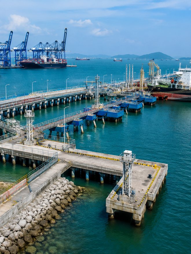
Marine & Pier Structures
Jetties, wharves, piers, and piles in the tidal zone, the most severe corrosion condition for reinforcing steel.
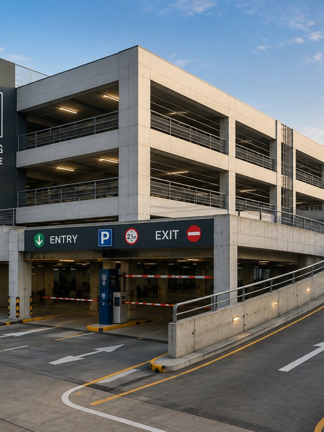
Parking Structures
Slabs, beams, and ramps exposed to water from tires, floor-washing chemicals, and constant accumulated moisture.

Hospitals & Public Buildings
Buildings that can't be shut down, needing repair work that helps reduce the risk of repeatedly disrupting occupants long-term.

Industrial Plants
Areas with chemicals, acid fumes, wastewater, cooling towers, and machinery-support structures that need uninterrupted production.
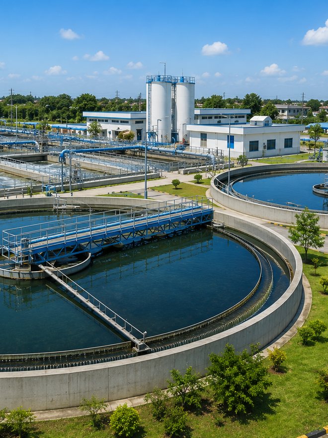
Water Treatment
Treatment basins, water tanks, and structures permanently exposed to water or constant wet-dry cycling.
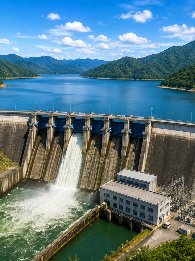
Dams & Reservoirs
Irrigation structures needing a long service life that are difficult to access for maintenance.
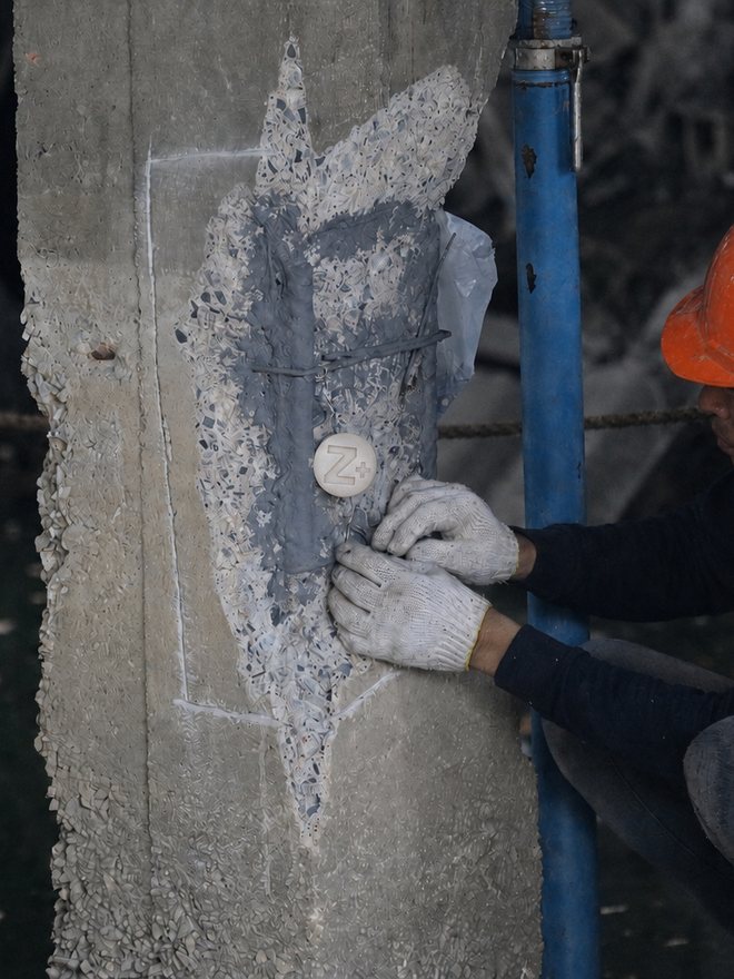
Concrete Repair Works
Installed alongside repair work to prevent the Ring Anode Effect and extend the life of the repair many times over.
An Engineering Partner
Not Just a Product Seller
Smart & Bright has worked with reinforced concrete structures for over 27 years, covering Concrete Repair, Epoxy Injection, Corrosion Control, Waterproofing, and FRP/CFRP Strengthening, so we understand problems from their deep root cause through to real site constraints and project owners' acceptance conditions.
Full Documentation
Ready to Tender
and Ready for Acceptance
We prepare a complete engineering documentation package so project owners, consultants, and main contractors can review and accept the work with confidence, for both government and private projects.
- ✓ TIS 3029-2563 certification (License 8496-3/3029)
- ✓ ISO 12696:2012 and ASTM B418 Type II reference documents
- ✓ Calculation sheet and installation drawing certified by an engineer
- ✓ Method Statement and Inspection & Test Plan
- ✓ QC records with before / during / after installation photos
- ✓ As-Built drawing and post-installation measurement report
3029
2563
Certified Manufacturer
LICENSE NO. 8496-3/3029
ASTM B418 TYPE II ZINC
DESIGN TO ISO 12696:2012
Engineering FAQ
The Galvanic Cathodic Protection system works by changing the reinforcing steel's electrochemical state to a cathode, which controls the ongoing corrosion rate within the designed area. Rust that has already formed does not disappear, but its spread is controlled, so it must be used together with removal of damaged concrete and proper cleaning of the steel surface.
When a repair is patched only at a specific spot, the new concrete at the repair differs in condition from the surrounding chloride-contaminated original concrete, causing reinforcing steel at the repair boundary to become a new anode (an incipient / ring anode) and corrode faster, cracking again. Installing SmartZinc Z+ along the repair boundary supplies protective current directly to the steel there, significantly reducing the risk of this phenomenon.
It depends on corrosion severity, reinforcing steel density, chloride content, moisture, and the desired service life. Coastal areas or continuously damp structures typically use Z+100G or higher. Our engineering team calculates the Steel Density Ratio and sets installation spacing to ISO 12696:2012 based on real site data.
No. The galvanic system works on the natural potential difference between zinc and steel, so it needs no external power source, no control cabinet, no electricity cost, and almost no maintenance, unlike ICCP systems, which require a maintenance team and continuous monitoring for their whole life.
We provide full service: Design · Supply · Installation · Inspection. We supply SmartZinc Z+ anodes along with a design engineering team and trained installation crews, covering everything from site survey and system design through installation, continuity testing, and delivery of QC and As-Built documentation.
It can be designed for 10–30 years, depending on the model selected, quantity and spacing, the structure's environment, the density of reinforcing steel to be protected, concrete resistivity, and the protective current needed for the risk level. It is not a fixed value for every project. The designing engineer states the projected service life in the calculation sheet delivered to the project owner.
Fully supported, including TIS 3029-2563 certification, ASTM B418 Type II and ISO 12696:2012 reference documents, a calculation sheet certified by an engineer, Method Statement, Inspection & Test Plan, QC records, and As-Built drawings. Contact our technical team directly to request a tender document package.
Talk to a
Corrosion Engineer
Before You Decide
Send us your structure's details and photos of any damage. The Smart & Bright engineering team will help assess the risk level, select a suitable model, calculate the installation quantity, and prepare a proposal with documentation for acceptance, with no charge for the initial assessment.
RESPONSE WITHIN 1 BUSINESS DAY · BANGKOK, THAILAND